
Overview
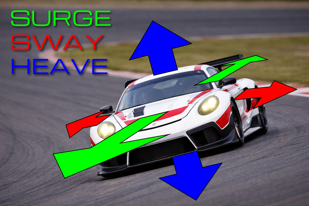
MAIRA G Tensioner is a DIY sim racing feedback system designed to simulate vehicle forces through the seat belts. By converting surge, sway, and heave accelerations into tensioner arm movement, the system dynamically tightens and relaxes the belts to represent braking, acceleration, cornering forces, and vertical impacts. Unlike motion rigs, which are especially effective at short impulse cues and rapid chassis movements but cannot continuously reproduce sustained G-forces, the G Tensioner can maintain belt pressure over time. This allows the driver to feel not only quick transitions, but also ongoing forces such as sustained braking, steady cornering load, and continued acceleration. The result is an additional layer of physical feedback that improves immersion and makes vehicle behavior easier to feel without requiring a full motion simulator.
Special thanks to Matthew Brittle and Chad McNeese for helping develop this system.
Here are some handy links to jump to the section you are interested in –
- Video
- Tools You Need
- Parts You Need
- Belts / Harness
- Belt Rollers
- 3D Printing
- General Assembly Instructions
- Nano Software Installation
- Arm Assembly Instructions
- Arm Mounting Instructions
- Sim Rig Mounting Instructions
Video
First, here’s a fun video to watch, to see the seat belt tensioner in action!
Warning – there’s a bit of profanity in the video, so if there are kids around you’ll want to wear headphones or mute the audio.
Tools You Need
- A wire stripper.
- A soldering iron in order to put in the heat-set inserts, and to tin some of the wires.
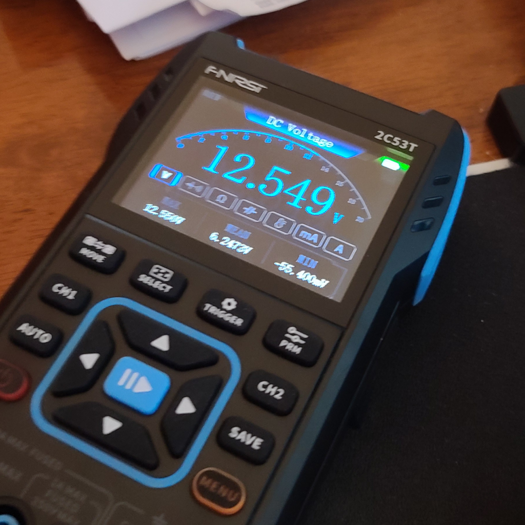
- A multimeter to check the voltage that the power supply is set to.
- Allen wrenches of various sizes.
Parts You Need
These are the parts that you need to purchase. Prices listed are as of 3/29/2026.
- Arduino Nano – $15.99 for 3 (you only need one)
https://www.amazon.com/dp/B07G99NNXL - Nano Terminal Adapter Expansion Board – $8.79 for 3 (you only need one)
https://www.amazon.com/dp/B073JGV87F - 150KG Digital 180 Degree Servo with Servo Arm – $36.99 each (you need two)
https://www.amazon.com/dp/B0CCP19V4J - AC 110V/220V to DC 12V 20A 240W Universal Power Supply – $15.99
https://www.amazon.com/dp/B010CVJAYS - 3-Prong Power Cord with On/Off Switch – $9.99
https://www.amazon.com/dp/B0DRNP6GL8 - Noctua NF-A4x10 PWM Fan2 – $15.95 each (you need two)
https://www.amazon.com/dp/B07DXRNYNX - USB Extension Cable – $6.99 for 10 feet
https://www.amazon.com/dp/B0FDQF5N7K
Total cost for the above parts will be around $164.
You will also need the following –
- Heat Set Inserts (see table below)
- Two M2.5x6mm screws
- Eight M3x16mm screws with flat washers and lock washers
- Eight M4x12mm screws
- Two M5x20mm screws with flat washers and lock washers
- Four M8x16mm screws with flat washers and lock washers
- Four M8 T-Nuts with ball springs
- 22 AWG solid wire
- Zip ties
| Screw | Height | Outside ⌀ | Hole ⌀ |
| M2.5 | 6mm | 4mm | 3.1mm |
| M3 | 5.7mm | 4.6mm | 3.9mm |
| M4 | 8.1mm | 6.3mm | 5.4mm |
| M5 | 9.5mm | 7mm | 6.1mm |
Here are some links to purchase these, if you don’t already have them.
- Heat Set Inserts – $12.99 for the kit
https://www.amazon.com/dp/B0FWWVT9J7 - Assorted Metric Screws – $17.99 for the kit
https://www.amazon.com/dp/B0GHWZPDRY - M8-1.25 x 16mm Socket Head Cap Screws – $13.49 for 40
https://www.amazon.com/dp/B0DDKDMVLD - M8 x 24mm OD Flat Washers – $9.49 for 50
https://www.amazon.com/dp/B0FQHZQ7QB - M8-1.25mm Metric Hex Nuts – $8.66 for 50
https://www.amazon.com/dp/B0DN272MRH - M8 T-Nut with Ball Spring – $14.99 for 50
https://www.amazon.com/dp/B0D91HFTF4 - M8 Steel Split Lock Washers & Flat Washers – $11.99 for 50
https://www.amazon.com/dp/B07Y5ZFRMC - 22 AWG Wire Solid Core Hookup Wire – $15.89 for 180 feet
https://www.amazon.com/dp/B07TX6BX47 - Assorted Zip Ties – $5.99 for a boatload
https://www.amazon.com/dp/B0C2Z4L3S6
Belts / Harness
If you do not have belts on your sim rig yet, you can get a nice 6 point harness from Top Street King on eBay for about $30. I do strongly recommend having a 5 or 6 point belt system (the 5th/6th belt is called a “submarine” belt). This is crucial to getting the maximum experience from the seat belt tensioner, as the submarine belt will prevent the lap belts from rising when the G Tensioner pulls on it, forcing the shoulder belts into your body instead of up and over your shoulders.
https://www.ebay.com/itm/182387126541
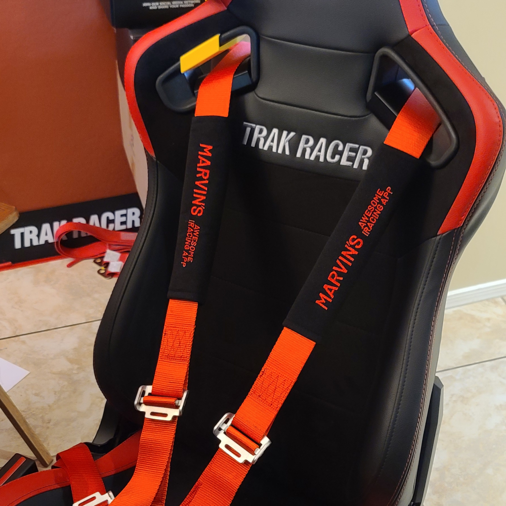
You can also get custom seat belt sleeves from UniquetoyouByTracy on Etsy ($43). I have gotten mine and can whole-heartedly give my seal of approval! Here’s how to order yours:
- Add their “Create business logo or design” product to the cart, selecting “Basic”.
- Add two “Custom Seatbelt Sleeve: Personalized Car Accessory” to the cart.
- Place the order and send your logo to Tracy via Etsy message.
Belt Rollers
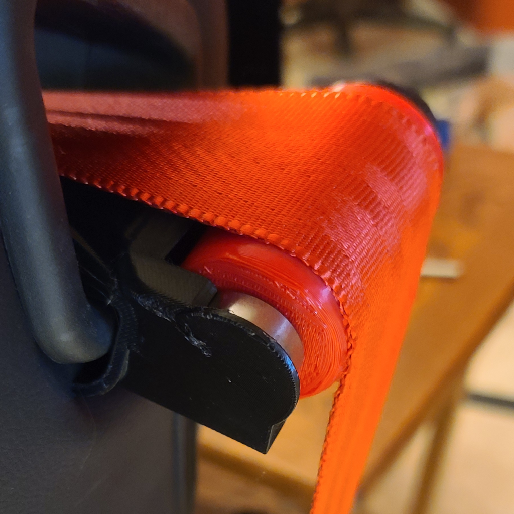
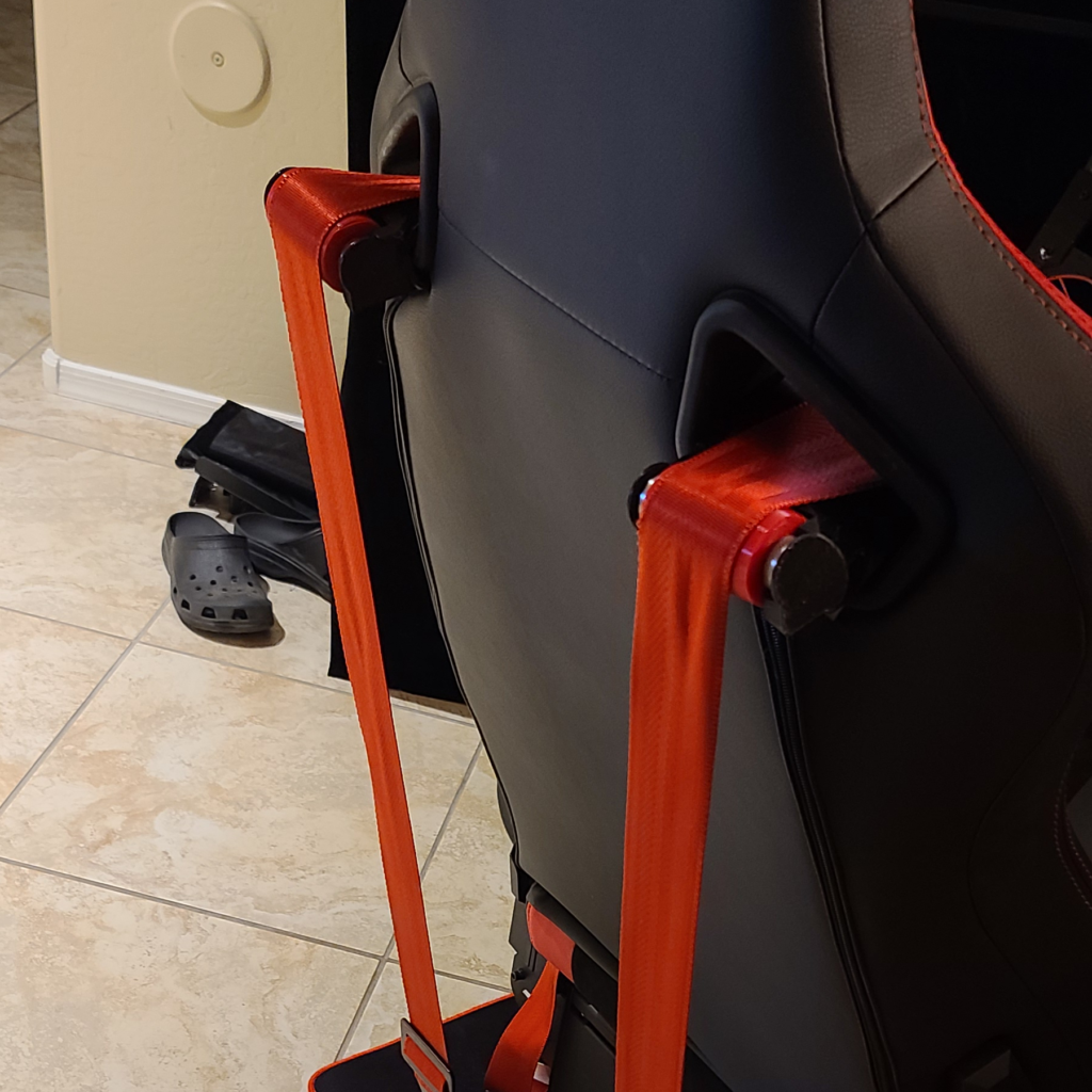
I also strongly recommend getting belt rollers for your seat pockets (the holes that the shoulder belts go through). I have custom-created rollers that fit the seat pockets of my Trak Racer Recliner Sim Racing Seat. If you have that same exact seat, you’re in luck – here are the 3D print (STL) files for the belt roller system.
You will also need four 608 ZZ Ball Bearings (8mm x 22mm x 7mm). Here’s a handy link to those ($5.79 for 20)
https://www.amazon.com/dp/B07216D1SZ
3D Printing
Here is the 3D print file you need to use to print out some the necessary parts.
Bambu Lab 3MF File
This is recommended – all of the parameters are already set for you. The MAIRA logo is set up for you as well as the color changes. Feel free to swap out the MAIRA logo with your own.
Generic STL Files
Use these files instead, if you are unwilling to use Bambu Studio. You will need to manually set the printing parameters if you choose to use these STL files. I recommend starting with the pre-configured default “Strength” setting in your slicer, making sure that it generates at least 6 walls and a strong infill. You will also need to enable regular supports to small portions of the front half and the arms.
There are 3 main parts to print:
- Rear Half
- Front Half
- Arms
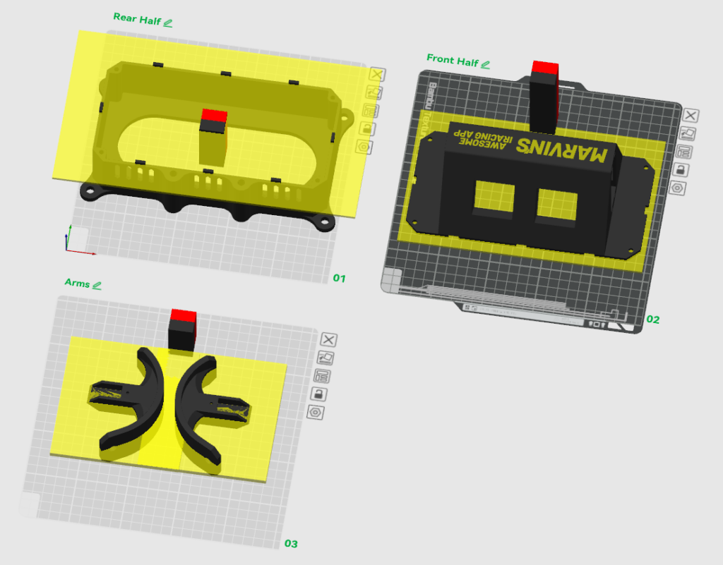
You will need to print all of these parts. The Bambu Studio file is set up to use 2 colors, but you can print with a single color if you don’t have an automatic material system for your printer.
You will use up a total of approximately 780 grams of filament. The total print time is approximately 23 hours on a Bambu Lab X1C.
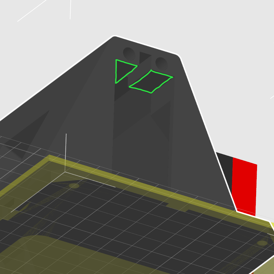
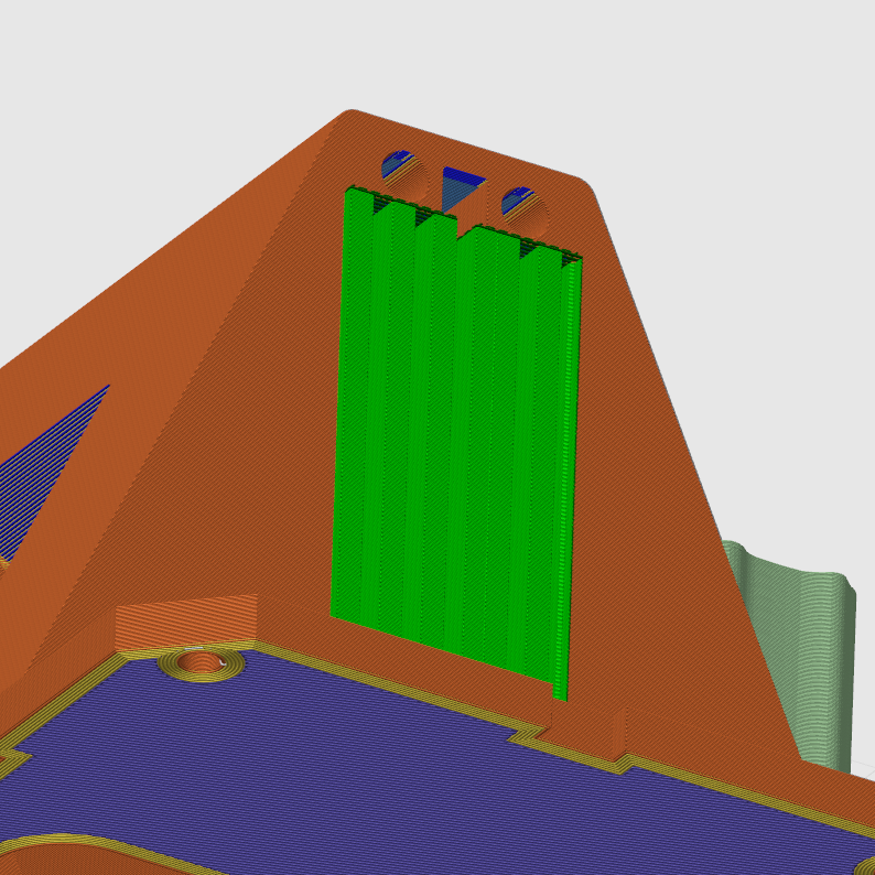
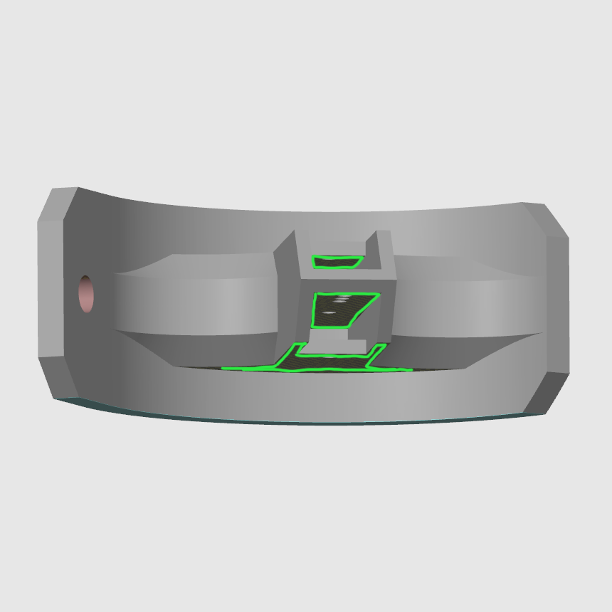
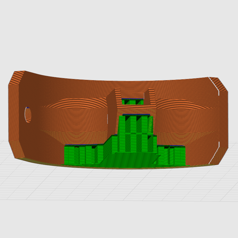
Supports
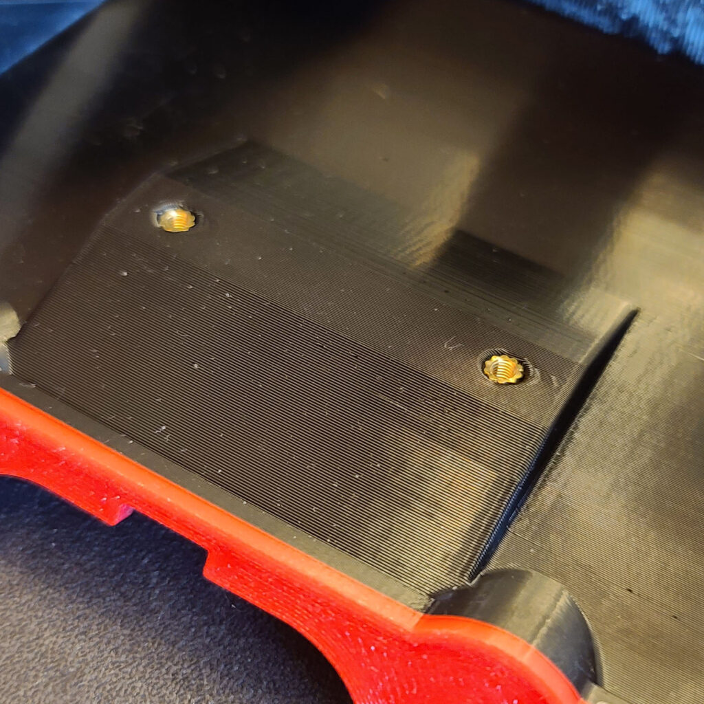
If you are not using Bambu Studio, you will need to manually paint in where the supports should go. Use regular supports. For the front half, you only need supports on exactly 4 faces – see the first image below for 2 of them. The other 2 are the same faces on the other side. For the arms, you will need supports as shown.
General Assembly Instructions
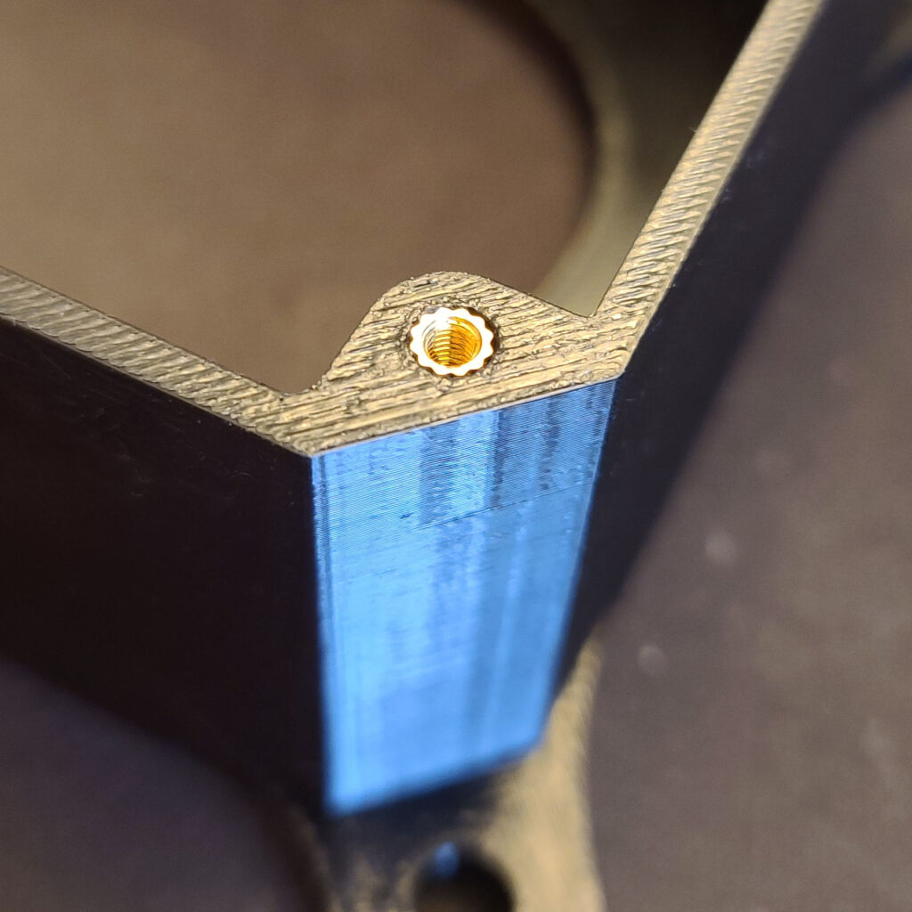
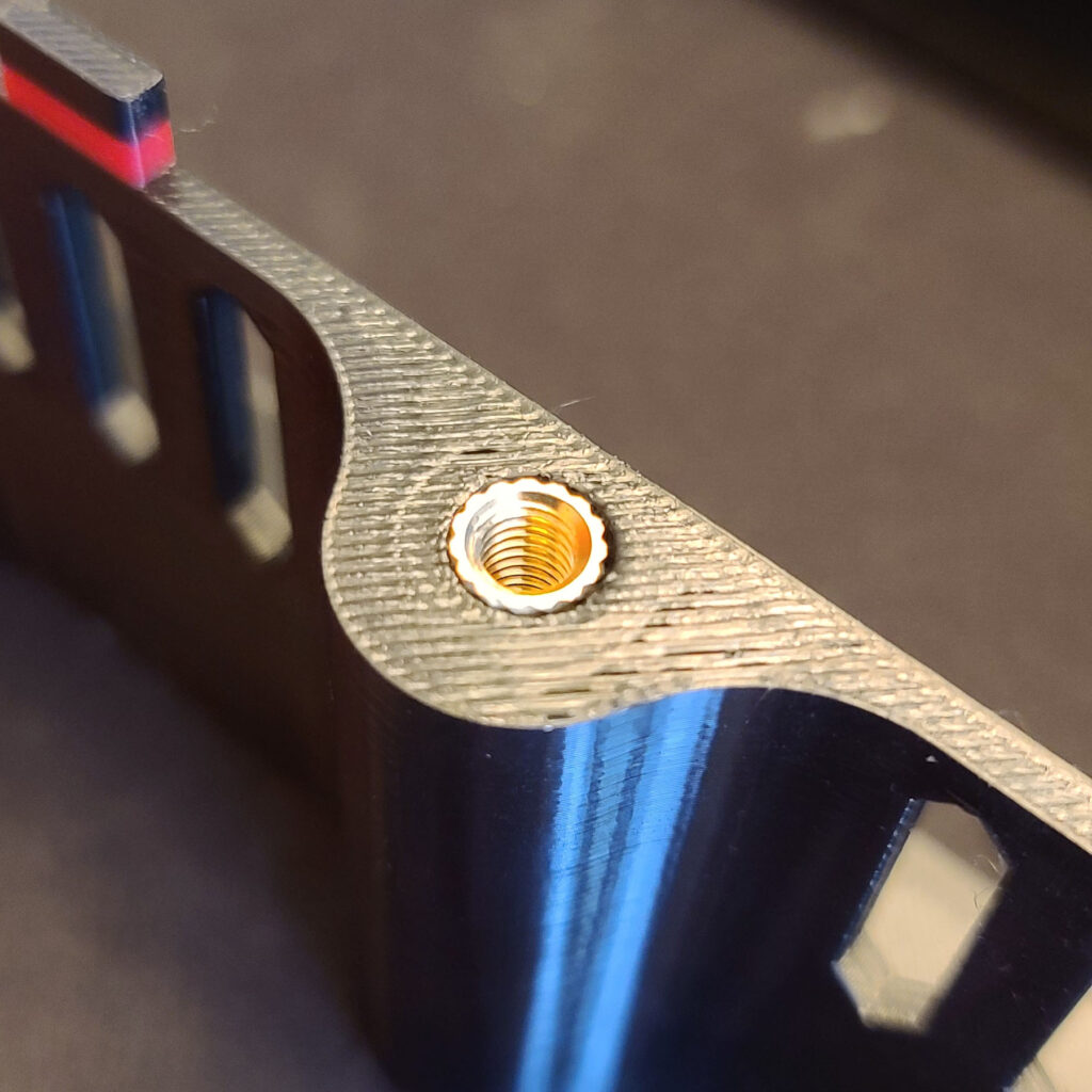
1. Install the heat-set inserts into the 3D printed rear half –
- Four of M3 H5.7
- Two of M5 H9.5
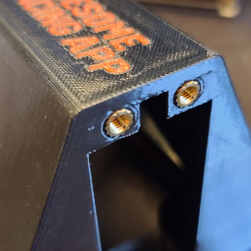
2. Install the heat-set inserts into the 3D printed front half –
- Eight of M4 H8.1
- Two of M2.5 H6
3. Push the open end of the 3-Prong Power Cord through the hole in the rear half. Note that there is a slot for the disc on the green wire to go through.
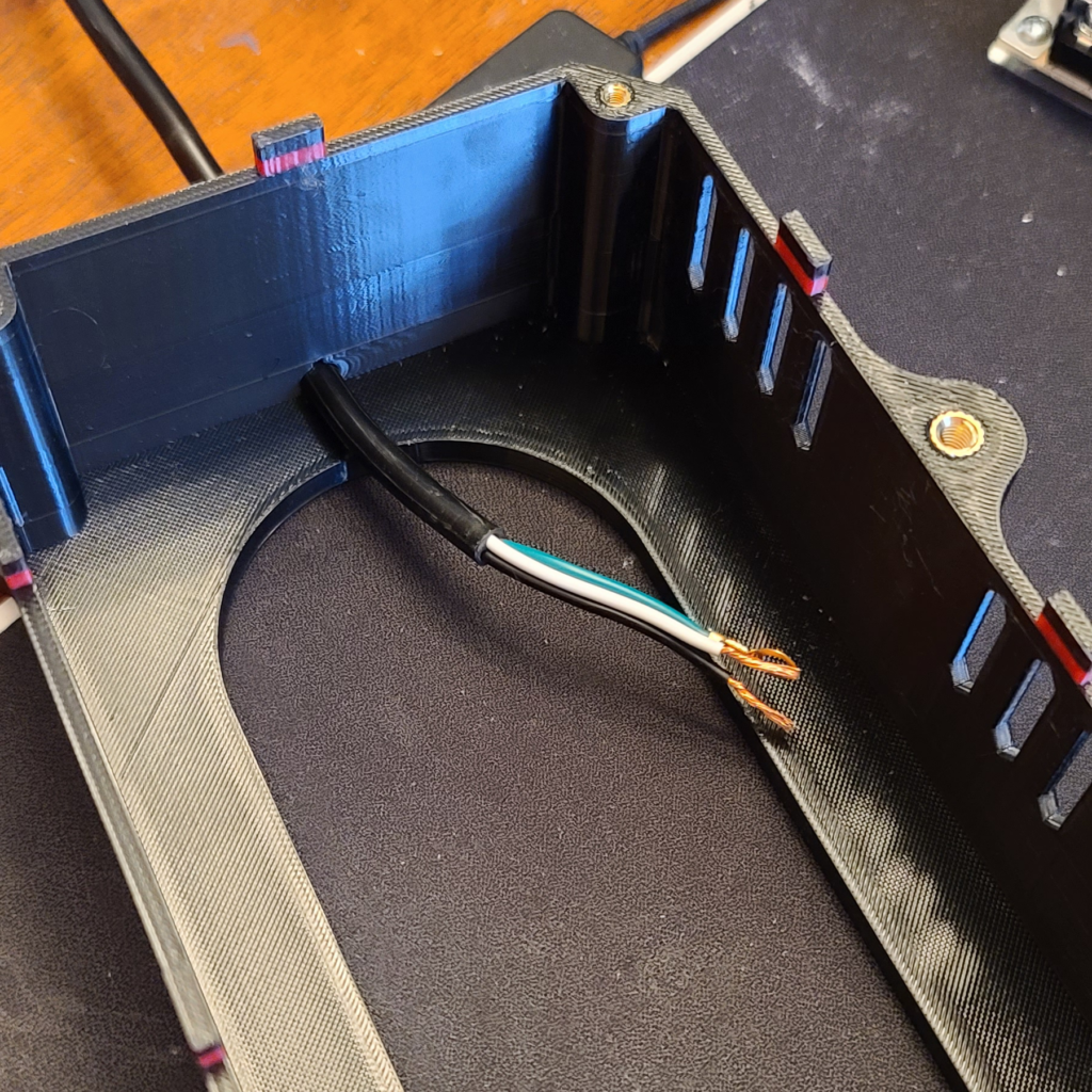
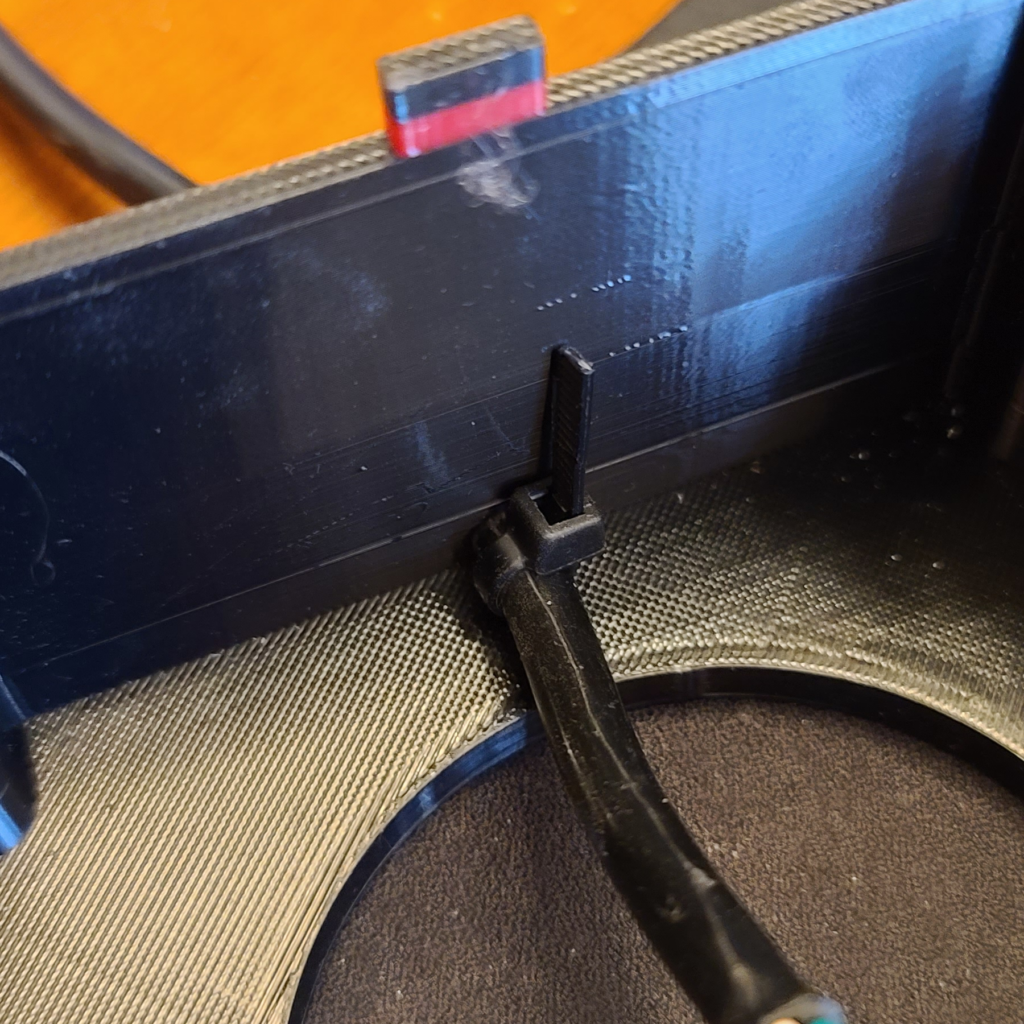
4. Zip tie the power cord wire as shown, to prevent the power cord from being accidentally pulled out.
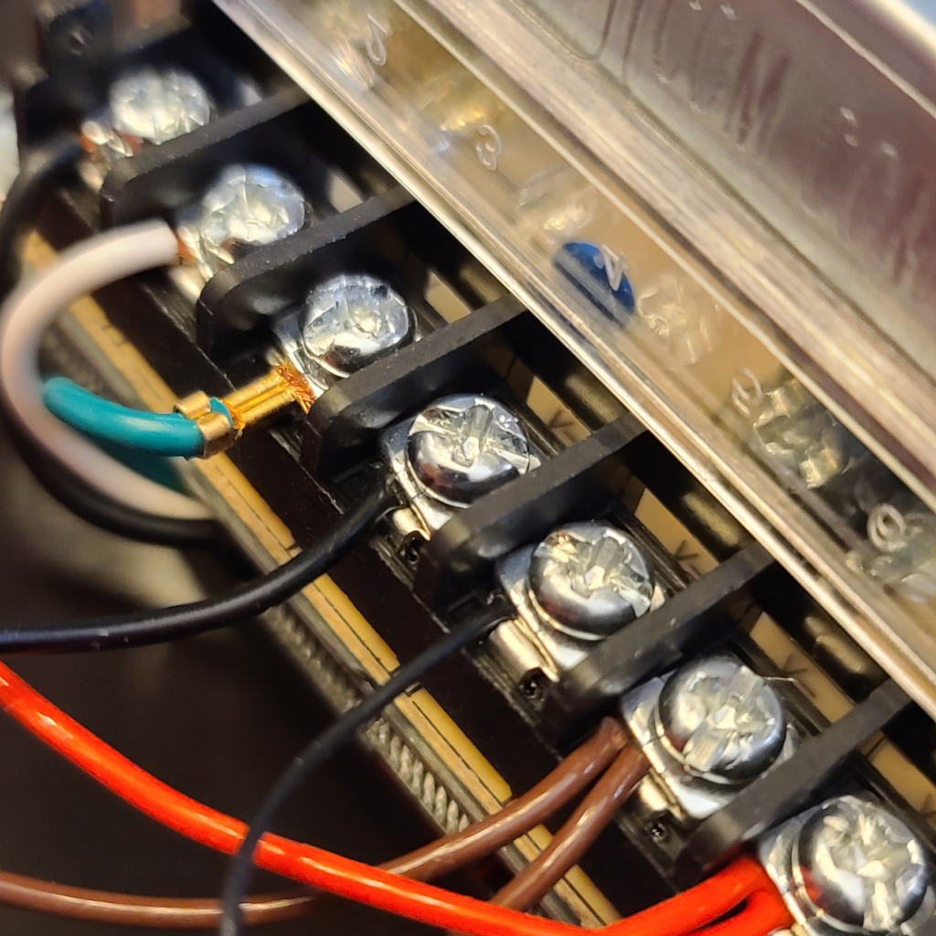
5. Connect the white, black, and green wires to the power supply unit as shown. The black wire should go to the “L” (line) slot. The white wire should go to the “N” (neutral) slot. The green wire should go to the ⏚ (ground) slot.

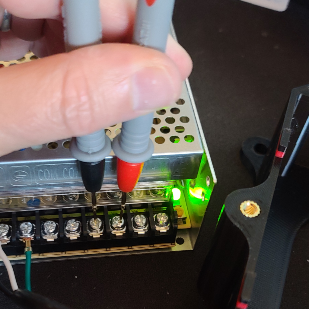
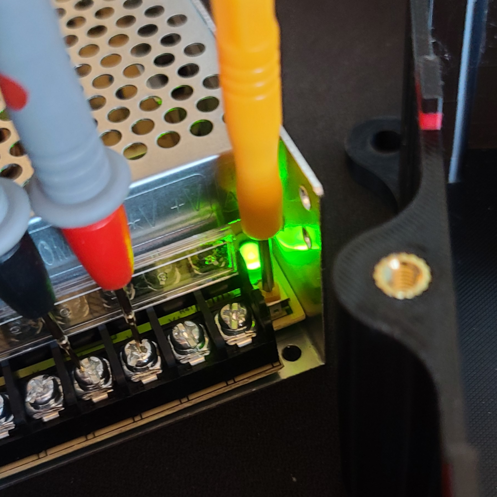
6. Plug the power cord into an outlet and temporarily turn on the power supply. Set your multimeter for DC voltage, and check the voltage by touching any of the COM and V+ slots with your multimeter probes. Adjust the beige colored screw slowly to get as close to exactly 12 volts as possible. Turn off and unplug the power supply when done.

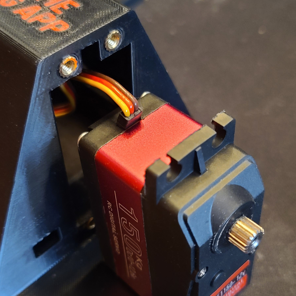
7. Slide in both motors into the top half. There is a notch to allow for the motor wires to pass through. Secure the motors with M4x12mm screws.
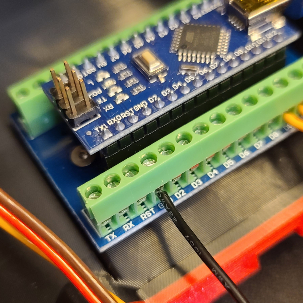
8. Attach the Nano terminal adapter expansion board to the top half using two M2.5x6mm screws. Make sure the D9 and D10 pins are facing you.
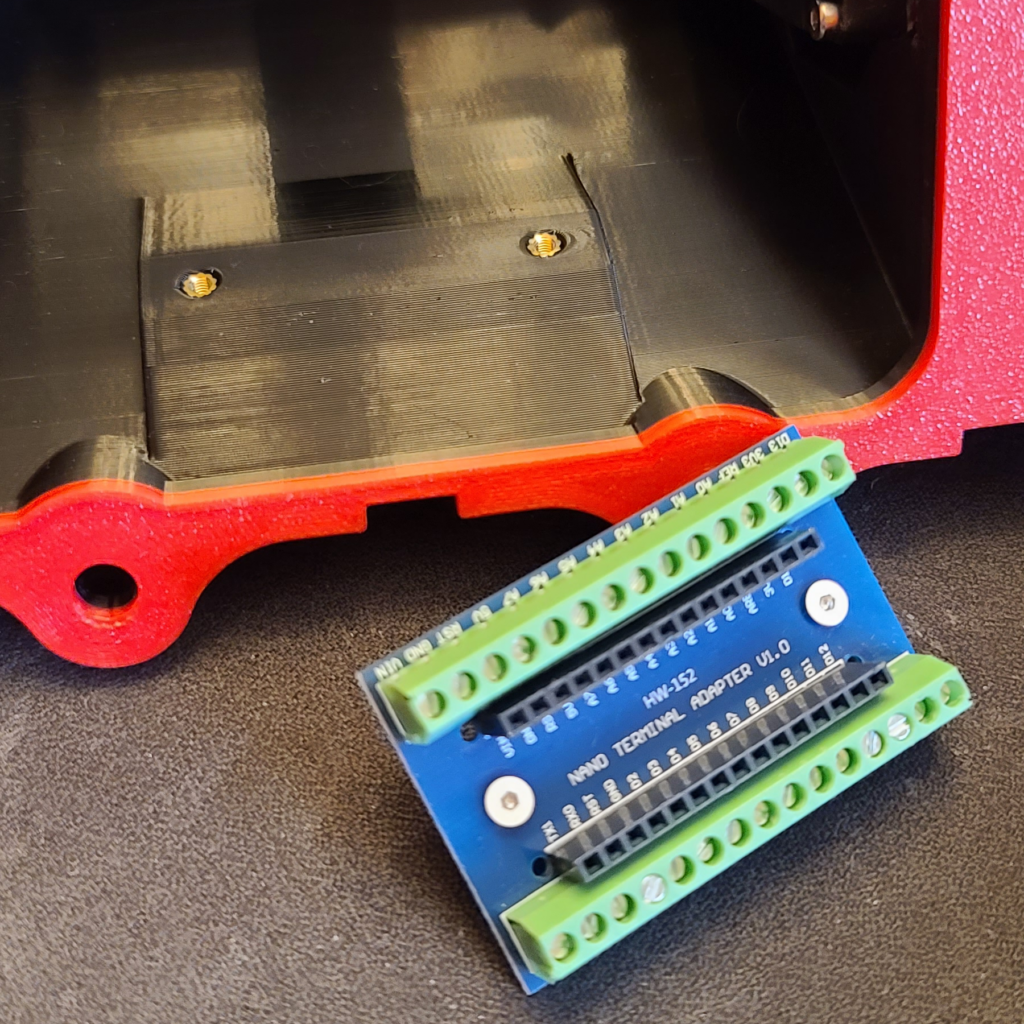
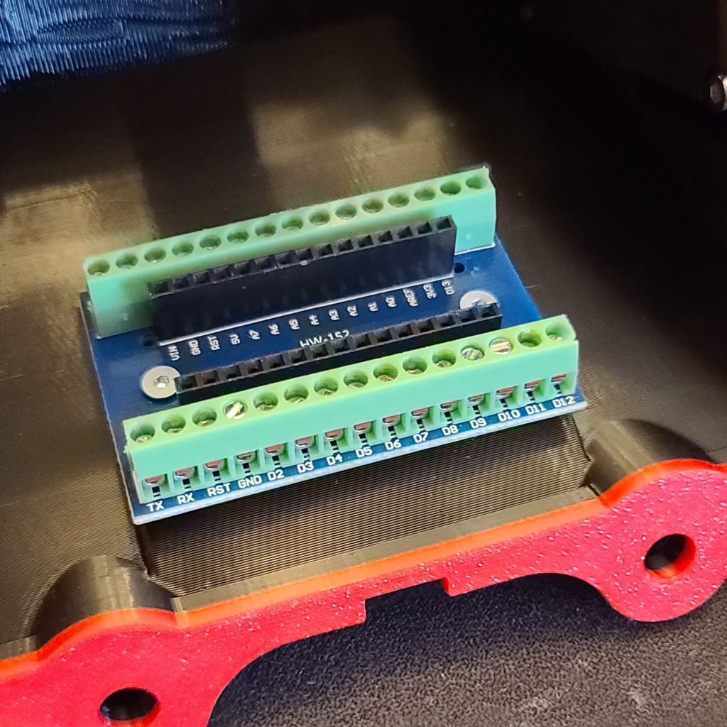
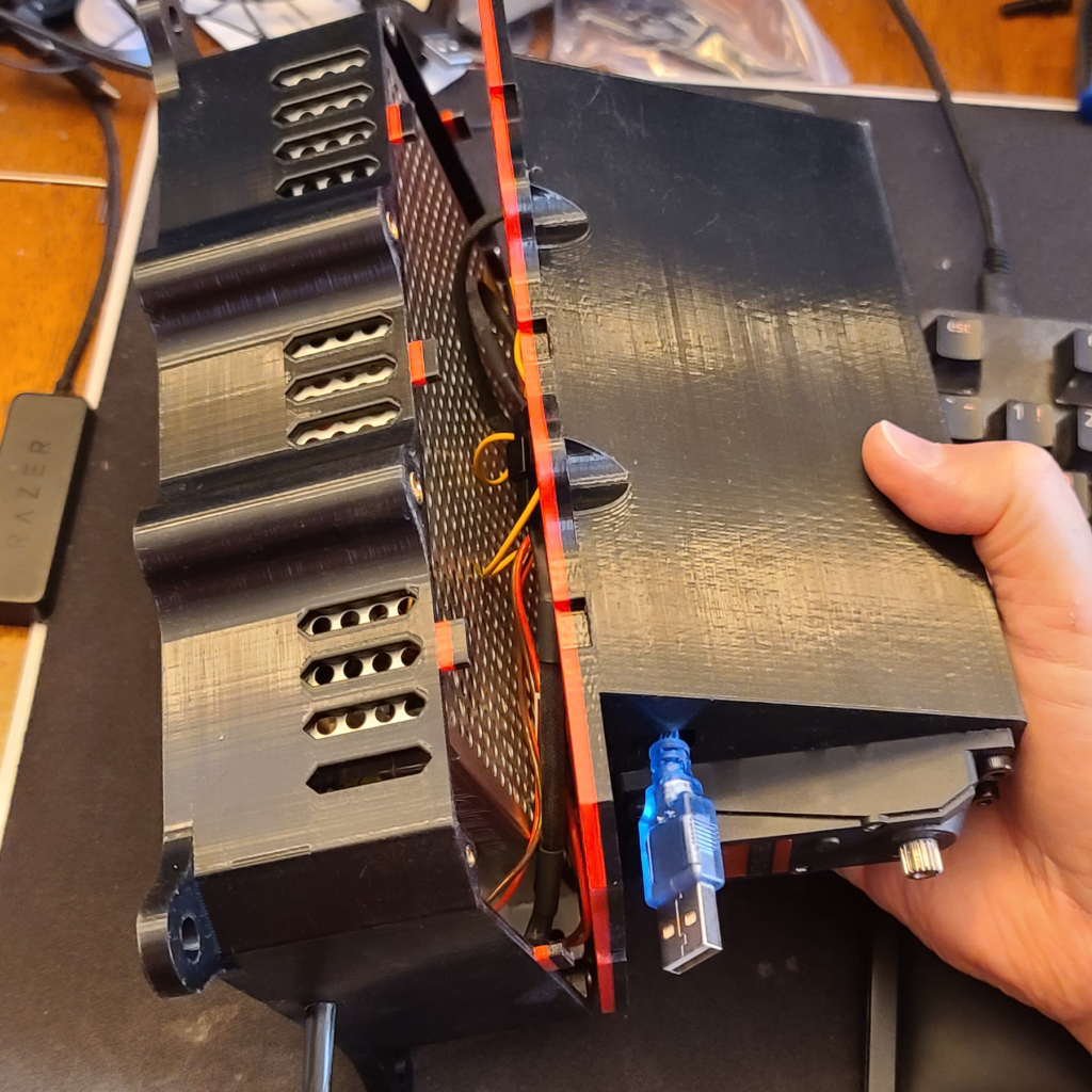
9. Install the Nano board. The USB port should be on your right.
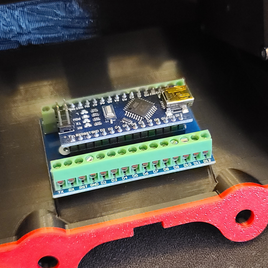
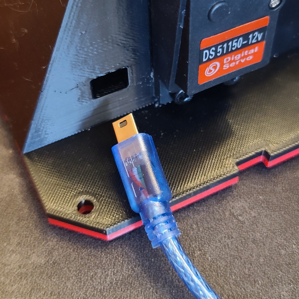
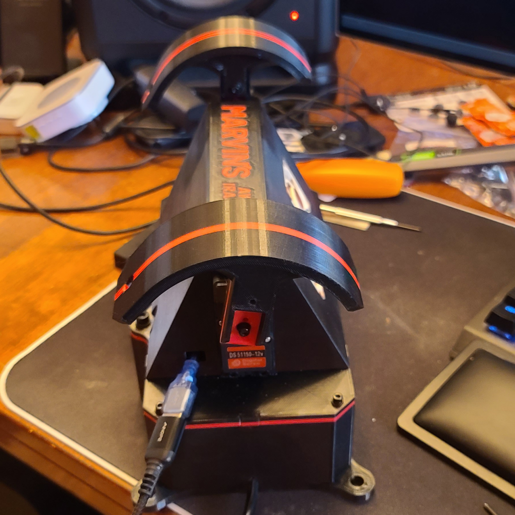
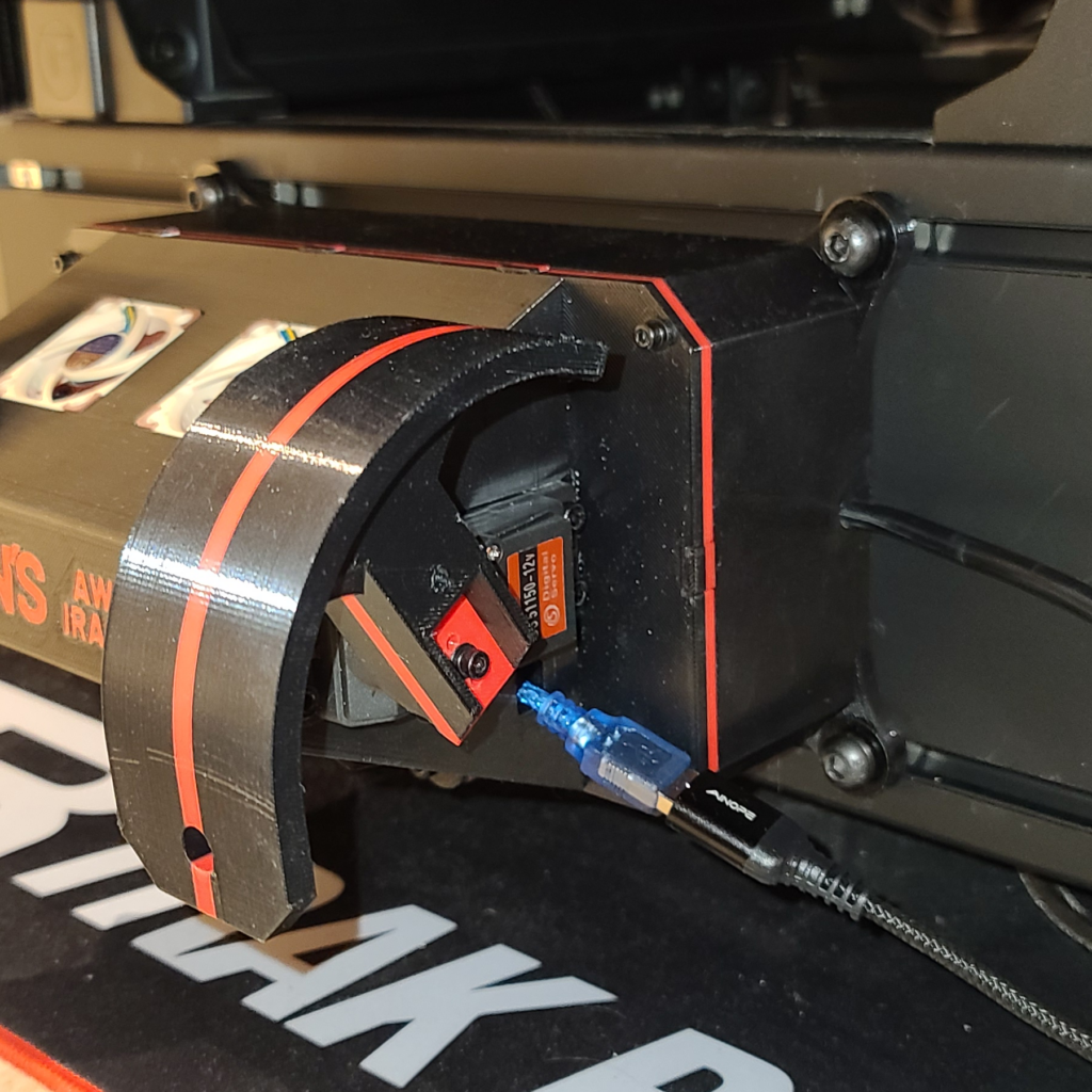
10. Push the small end of the short blue USB cable, that came with the Nano, through the square hole on the top half. Connect it to the Nano board, and zip tie the cable so it can’t be accidentally pulled out.
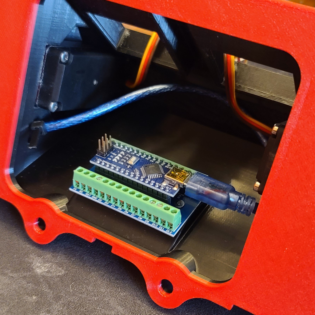
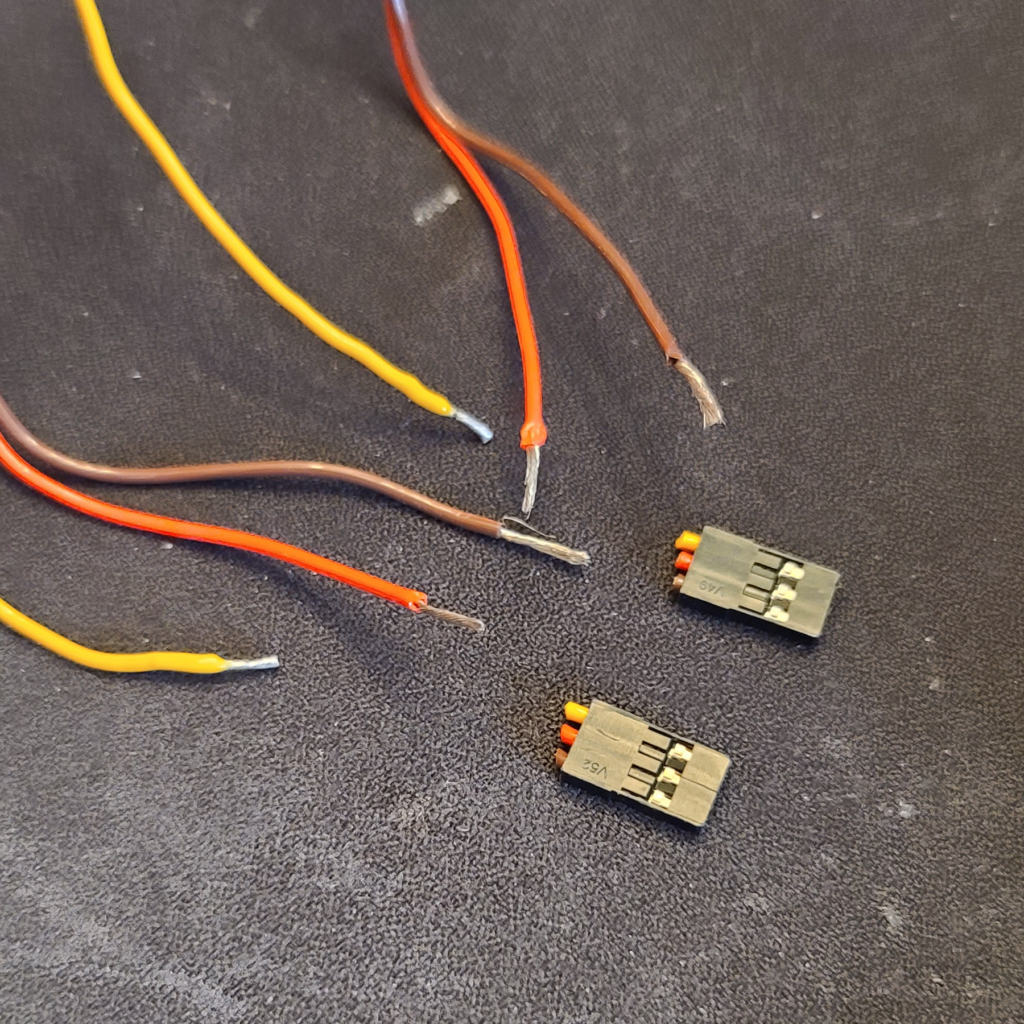
11. Cut the ends off of the motor wires, and use a wire stripper to expose about 1 cm of bare wire. You will want to tin the ends of the yellow wires. Trim the yellow wire so only about 5 mm is exposed.
12. Attach the yellow wire of the right shoulder motor to D9. Attach the yellow wire of the left shoulder motor to D10.
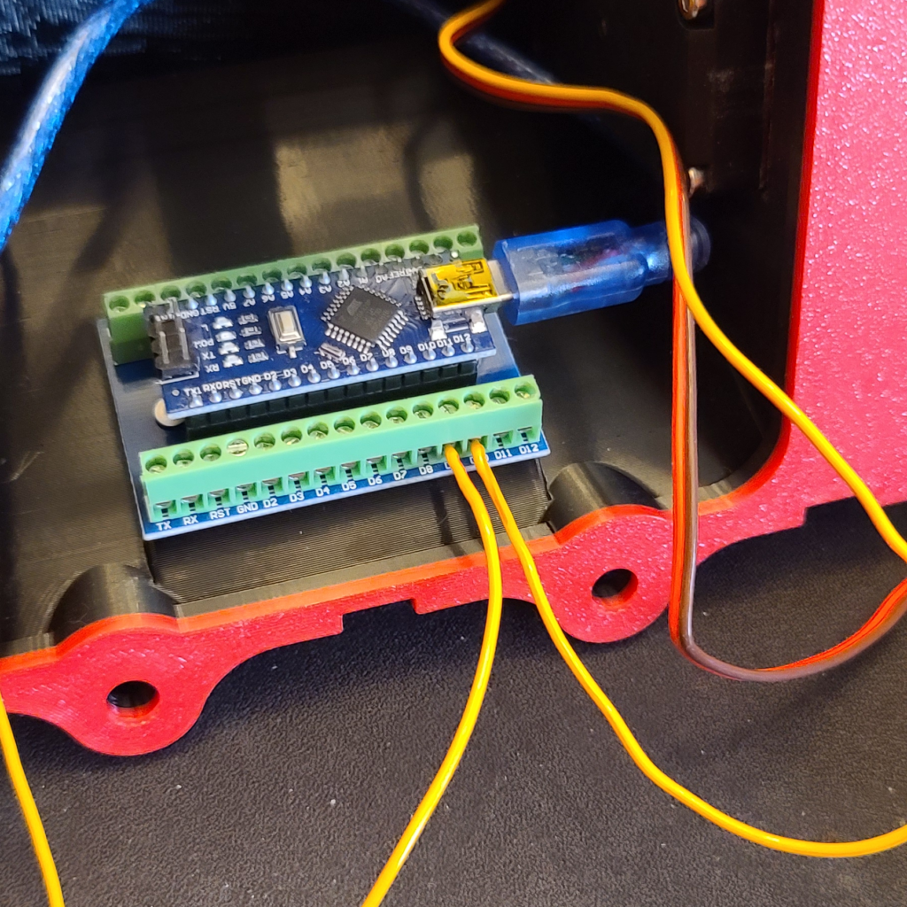
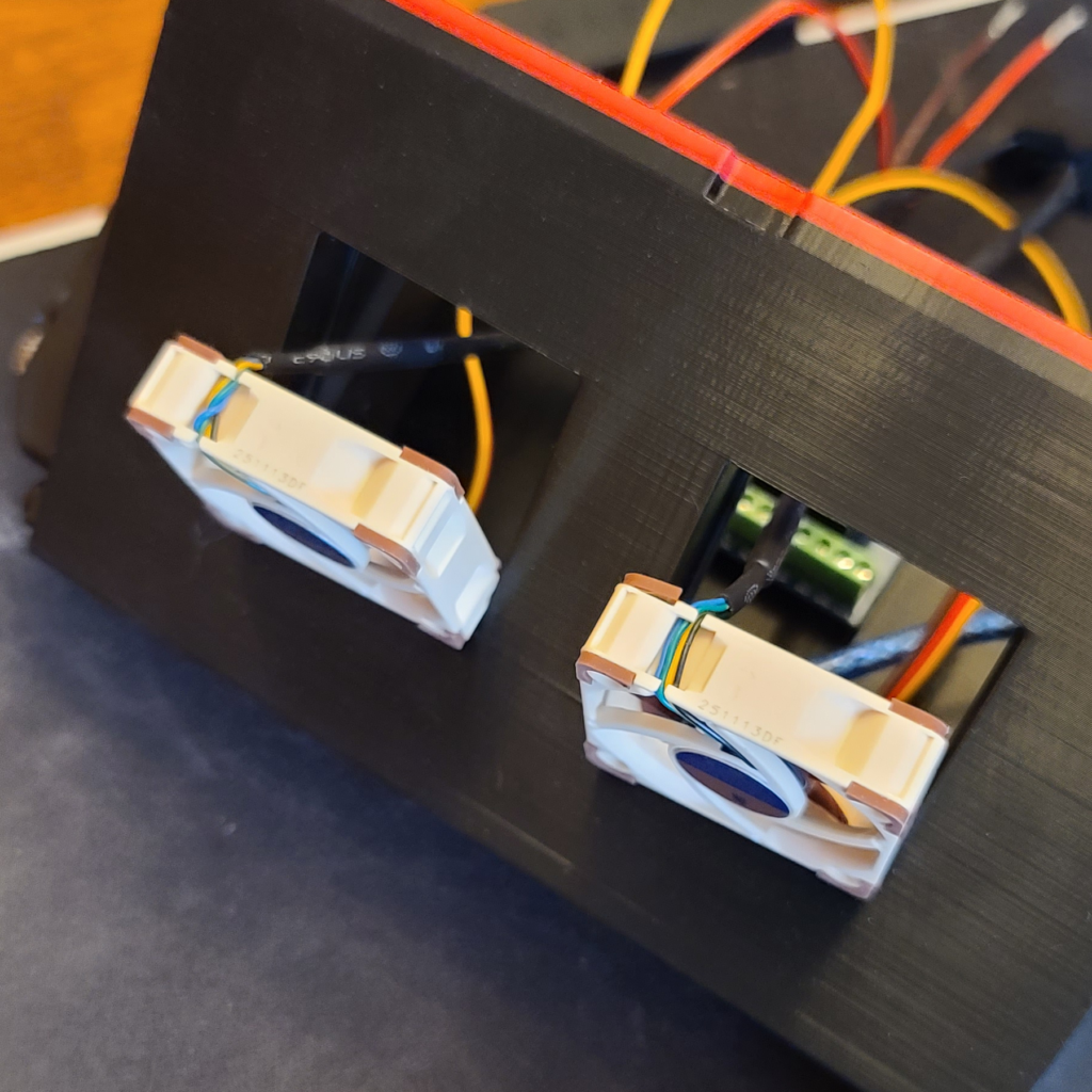
13. Slide in the two Noctua fans. Make sure to orient the fans so the label is facing out, and that the side with the wire is closer to the base of the top half.
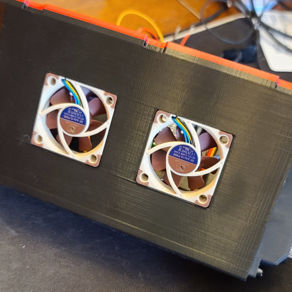
14. Connect both fans to a Y-cable (it comes with the Nano fans). Connect the Y-cable to the adapter that has the red and black wires. Use your wire stripper to expose the ends of the red and black wires.
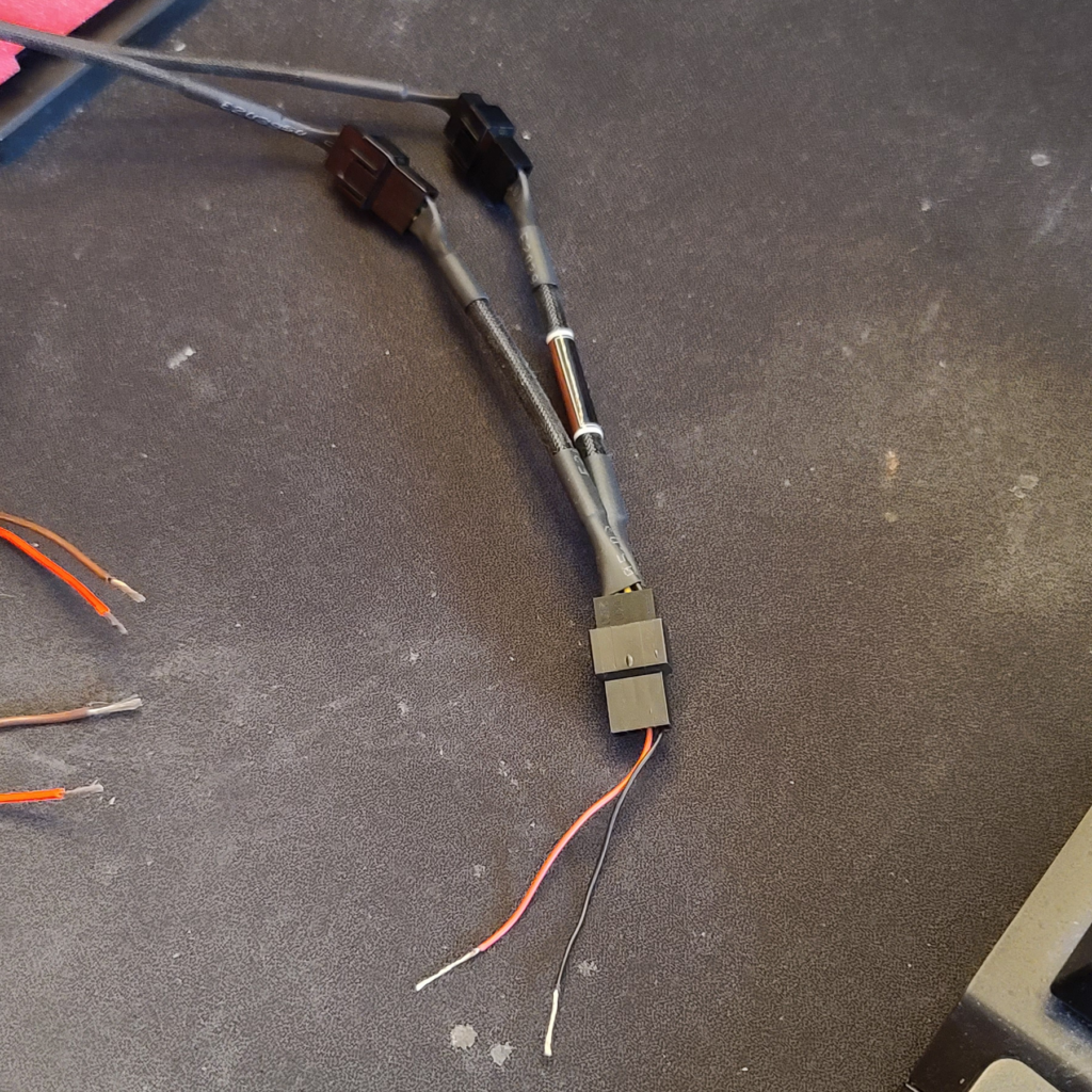
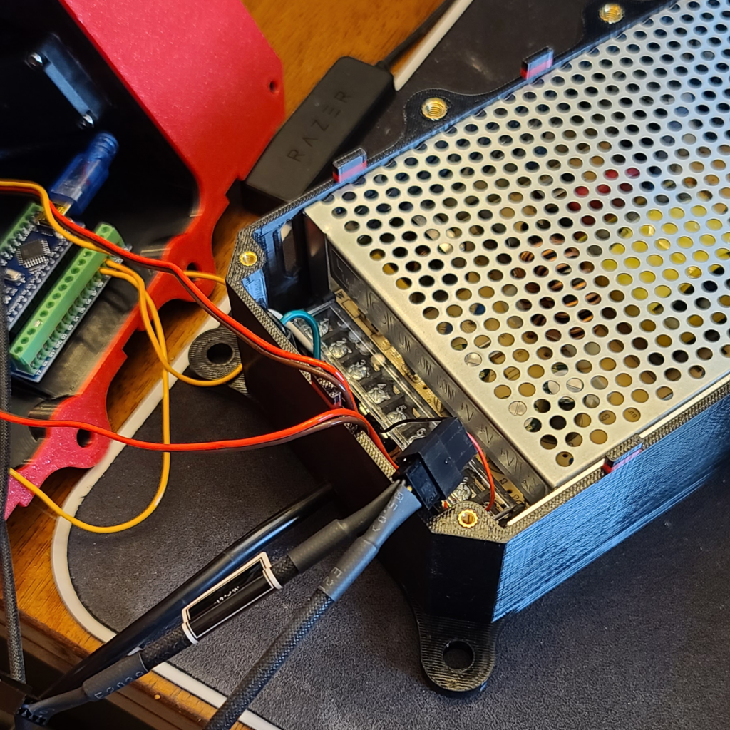
15. Time to wire stuff up –
- Connect the black fan wire to any negative (COM) slot on the power supply.
- Connect the red fan wire to any positive (+V) slot on the power supply.
- Connect the brown wires from the motors to any negative (COM) slot on the power supply.
- Connect the red wires from the motors to any positive (+V) slot on the power supply.
- You can connect both of the brown/red motor wires to the same slots.
Do a quick power-on test and check that both fans spin up.
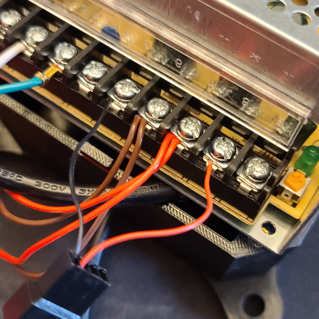
16. Cut about 10 inches of 22 Gauge solid wire. Use a wire stripper to expose about 1 cm of bare wire on one end, and 5 mm of bare wire on the other end. Connect the 5 mm end to the GND pin on the Nano. Connect the 10 mm end to a negative (COM) slot on the power supply.
17. Slide the power supply fully into the back half. Slowly position the top half on the back half, tucking in wires as you go. Make sure none of the wires are touching the fans.
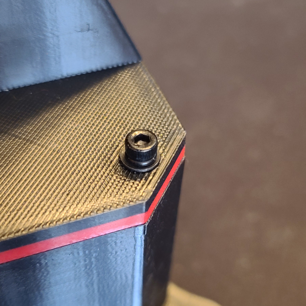
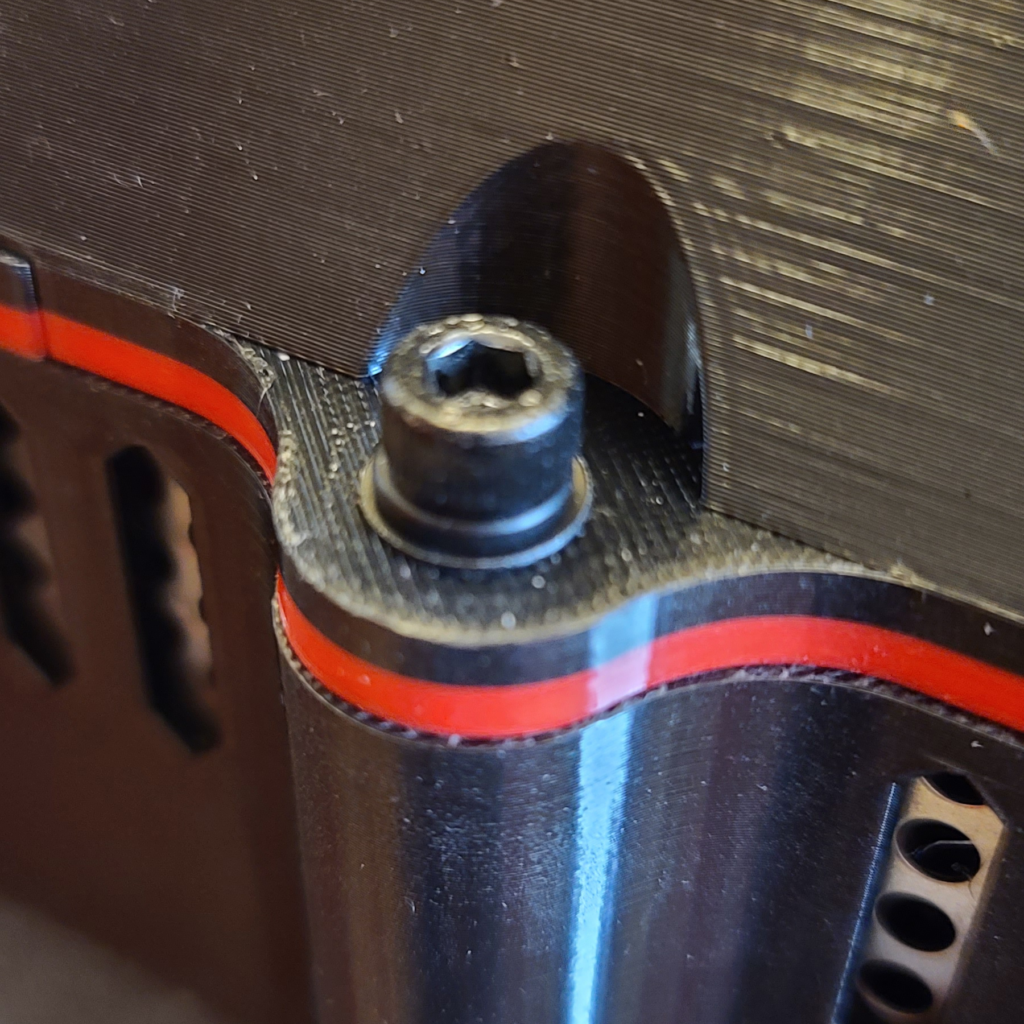
18. Secure both halves together using four M3x16mm screws with flat washers and lock washers. Further secure both halves together by using two M5x20mm screws with flat washers and lock washers.
Nano Software Installation
Now that you have the G Tensioner built, it is time to install the MAIRA G Tensioner software onto the Nano.
1. Download and install the Arduino IDE from here – https://www.arduino.cc/en/software/
2. Run the Arduino IDE.
3. Open up the SBT.ino file located in your Documents\MarvinsAIRA Refactored\SBT folder.
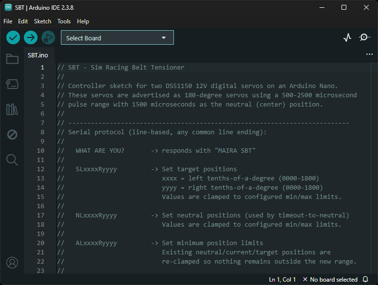
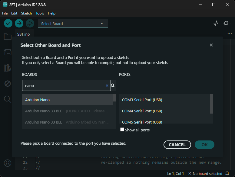
4. Open up the “Select Board” dropdown.
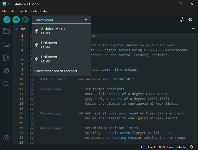
5. While keeping the dropdown open, plug in one end of the USB extension cable to your PC, and the other end to the G Tensioner. You should see a new device pop up in this dropdown.
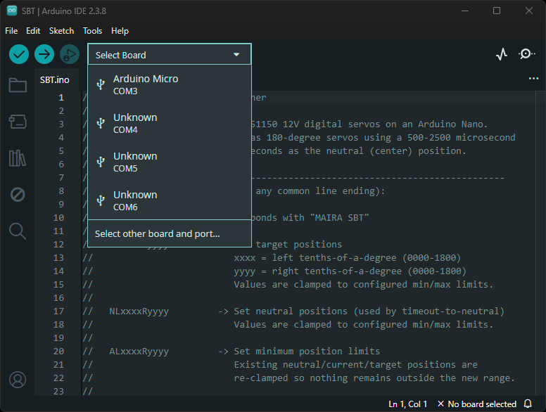
6. Click on the new device (COM6 in my case). It will ask you to identify the board. Select Arduino Nano.
8. Click on the arrow icon at the top left. This will cause the program to be compiled and downloaded onto the Nano.
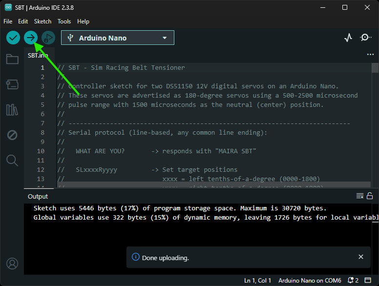
9. You are done with loading the program onto the Nano. Quit the Arduino IDE application.
Arm Assembly Instructions
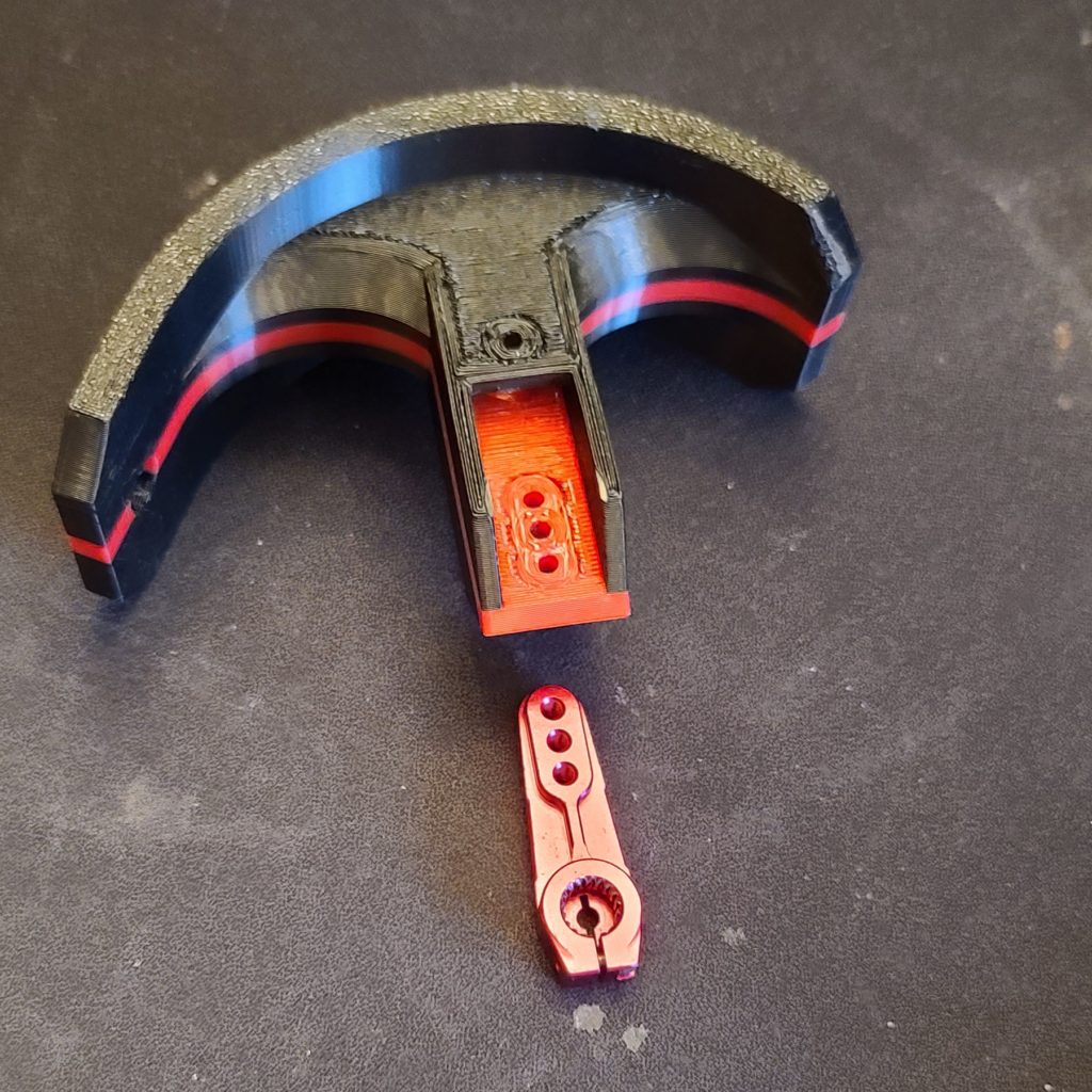
Before you get started, remove all the printed supports from both arms. The motors come with various levers. Pull out the red ones.
Important: Do not mount the arms to the motors at this time!
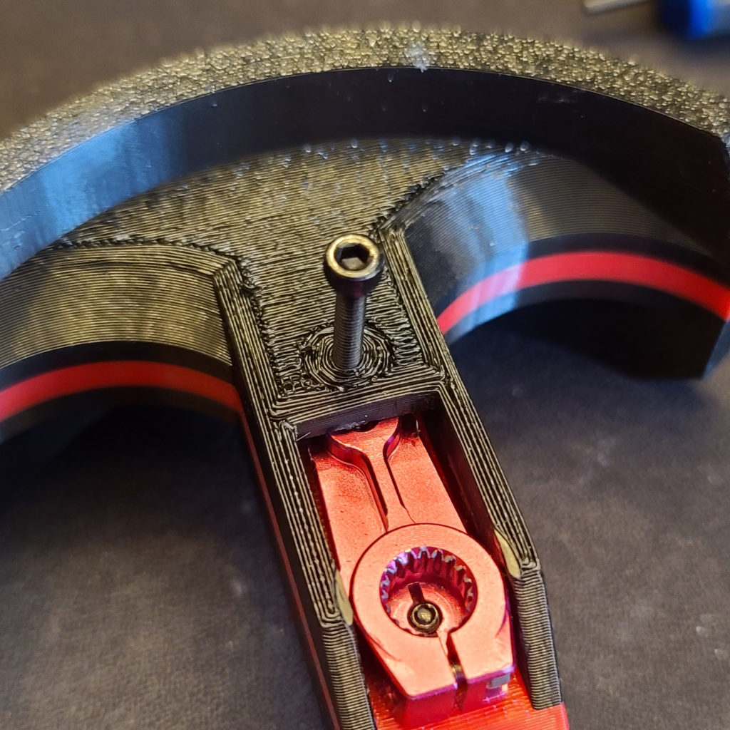
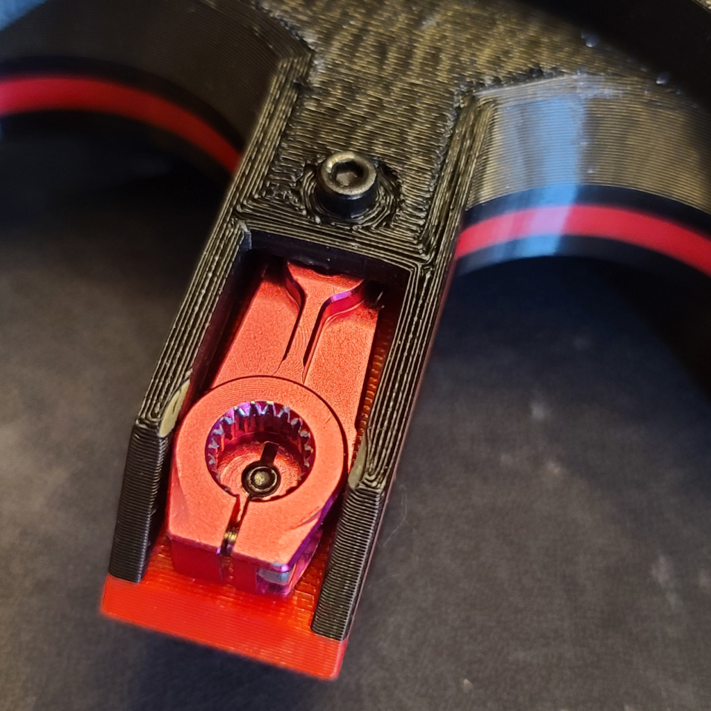
1. Attach the red lever to the 3D printed arms with a M3x16mm screws and flat washers and lock washers. But only go far enough to engage with the lever. We will tighten it up later when we actually put the arm on the motor.
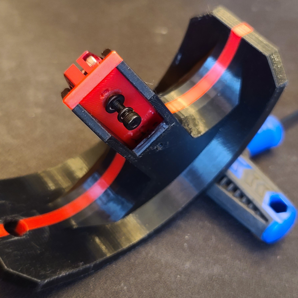
2. Screw in another M3x16mm screw as shown in these pictures – no flat washer or lock washer for this one. This screw is just to keep the arm from shifting around. Just screw it all the way in, but do not tighten this one.
Arm Mounting Instructions
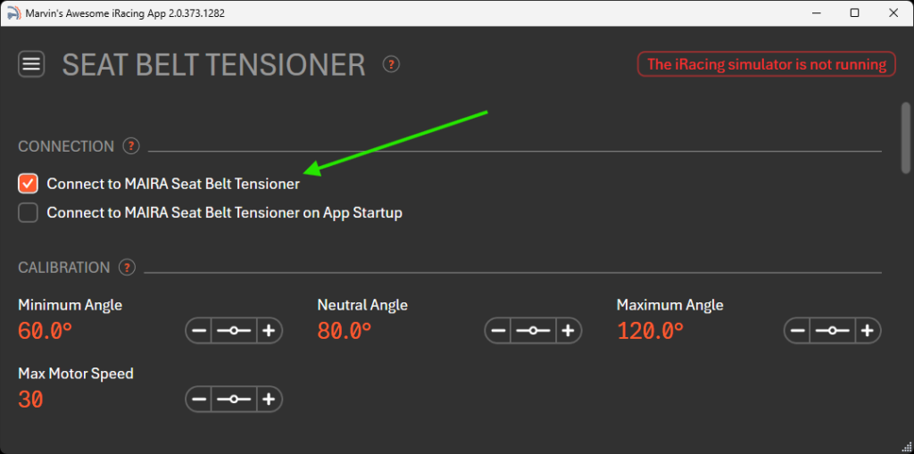
1. Plug in the G Tensioner and turn it on. Run MAIRA and switch to the Seat Belt Tensioner page. Click on the checkbox for “Connect to MAIRA Seat Belt Tensioner”. If the checkbox stays checked, then MAIRA was able to connect to your G Tensioner.
Do not run the iRacing simulator at this time.
2. Click and hold the mouse cursor on the slider for the “Minimum” setting and adjust the value of it by moving the mouse left and right. You should see the motors turning clockwise and counter-clockwise.
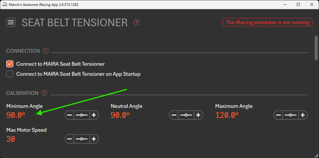
3. Click on the value for the “Minimum” setting, and type in “90” and hit enter. This will force the motors to rotate to the 90 degree (center) position.
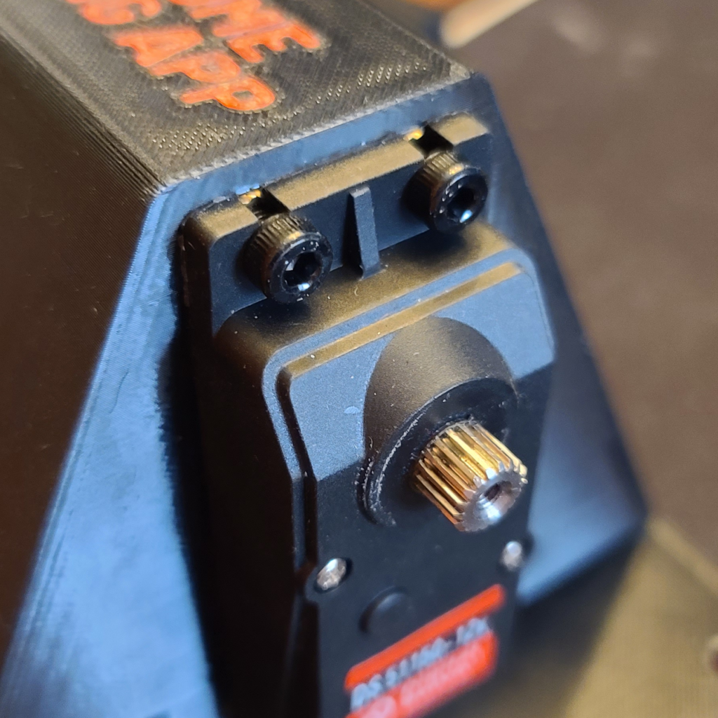
4. Now it is safe to mount the arms. Make sure the holes for the belt attachment are at the bottom! You want to mount the arms centered and pointing as straight as possible out of the G Tensioner. Tighten the two M3 screws. Also tighten the silver screws that came with the red levers.
5. Reset the minimum angle and neutral angle back to default values when you are done mounting the arms.
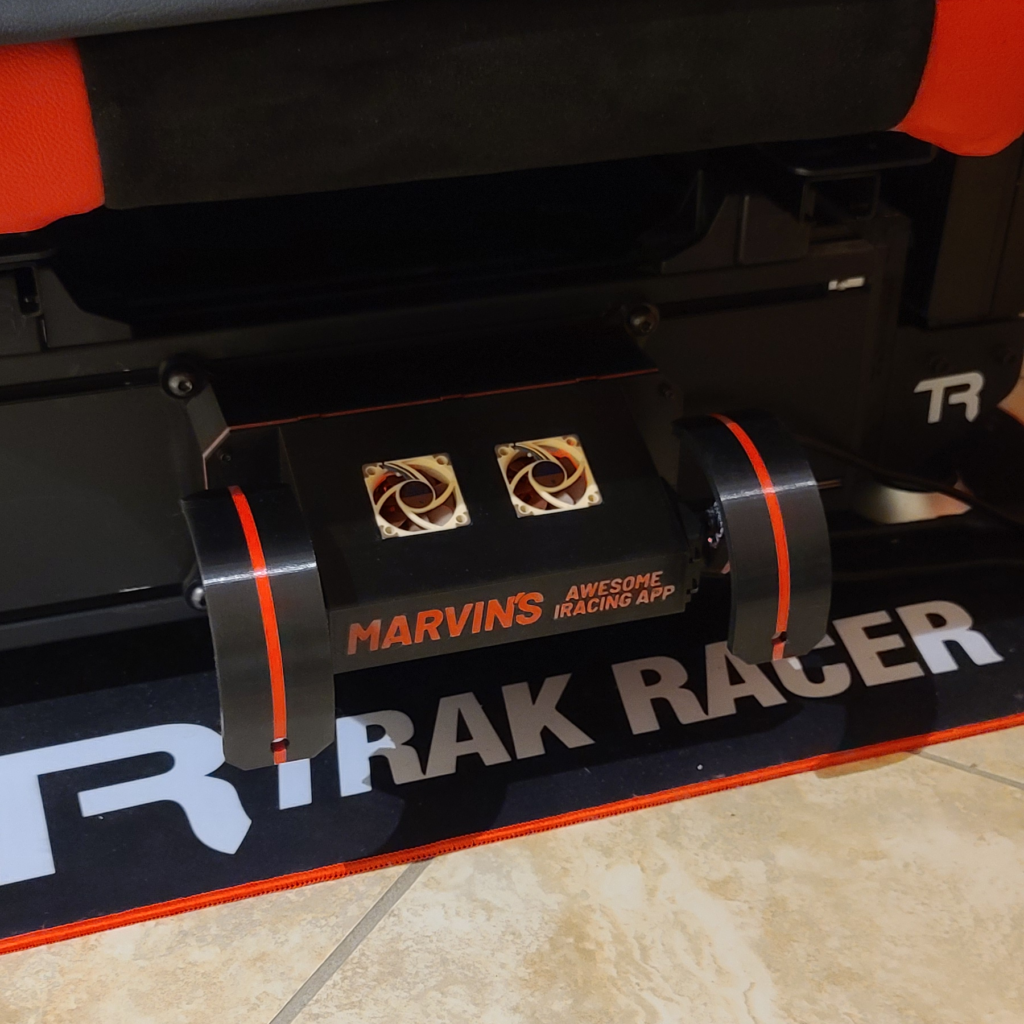
Sim Rig Mounting Instructions
Mounting the G Tensioner on your sim rig is pretty straightforward. Insert the t-nuts into the slots and use M8x16 screws with flat washers and lock washers to secure the G Tensioner. Make sure the G Tensioner is centered.
Tip: Run MAIRA and change the minimum position to move the arms out of the way for easier access to the M8 screws.
After you are done mounting the G Tensioner, take it out for a spin! I recommend taking the Mazda MX-5 out on the Lime Rock track with the following settings –
| Minimum Angle | 60° |
| Neutral Angle | 90° |
| Maximum Angle | 120° |
| Max Motor Speed | 30 |
| Surge | 2g |
| Sway | 2g |
| Heave | 2g with Subtract gravity ON & Invert ON |
Warning – make sure you have enough clearance for the minimum and maximum angles! The motors can and will destroy themselves by overheating if something is preventing the arms from reaching the minimum / maximum angles.